PIRA
5L20.26 RLC Circuits: LC Parallel Resonance
Click your browser's back button to return to the demo master list.
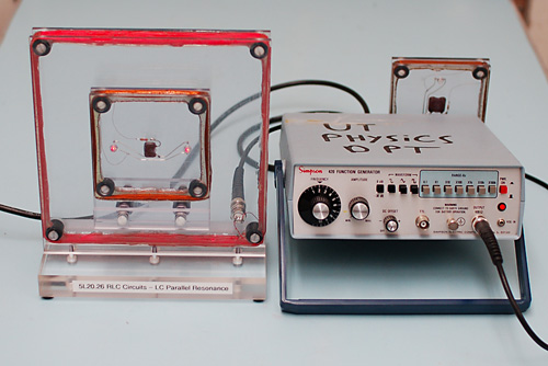
Photo of the Demonstration at the University of Texas at Austin.
Instructions / Notes:
-
The purpose of the demo is to show an example of a LC circuit that resonates only at a specific frequency.
- The demo makes good follow up to 5L20.10 RLC Phase Differences.
- The demo has a large primary coil powered by a function generator.
- A second coil/inductor is wired to a capacitor and a pair of light emitting diodes within its windings.
-
To attain resonance in the secondary LC coil, the function generator must be adjusted to a frequency of 210 KHz.
- At resonance two red light emitting diodes will fully light up.
Further Notes:
- The secondary coil is removeable to show that no wired connections exist between the two coils.
-
If needed. we offer a back-up secondary coil - which uses a different capacitor - and - unfortunately a different number of windings as the previous secondary coil.
- This second coil must be driven at a frequency of 360 KHz to attain resonance.
Last Updated 09/09 - University of Texas at Austin Physics Dept.
- All Rights Reserved.